Cet article n'est pas disponible en French. Affichez-la en English
Caution: These procedures should only be attempted by trained maintenance personnel.
Questions to ask:
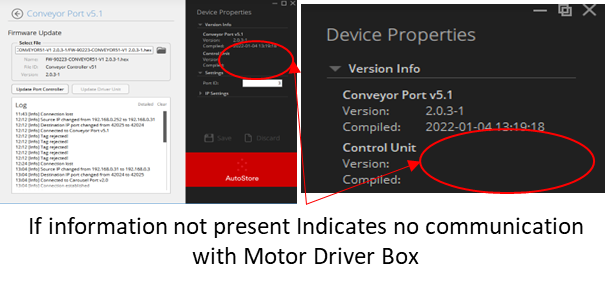
- What are the Firmware Versions?
- Controller
- Motor Driver Box
- Has the port been calibrated?
- When was the port last working?
- Can you ping the port from the Controller PC?
- Can we request information to this port in the Console?
- Is there a bin in the port?
- Is it overweight?
- Can we remove the bin from the port?
- Can manual moves be performed?
- What are the HW Config settings? (There is a FW bug in HWConfig before Fall green train 2024 where the Source ID does not get automatically updated)
Pre-Power Checks
- Inspect the port to verify that all cables are properly laid out and correctly fastened.
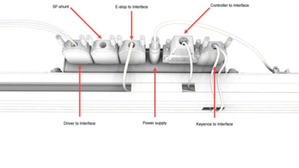
- Make sure all connectors are securely inserted and fastened into their sockets.
- Make sure that the drive shaft can move freely back and forth.
- Check for any play with the weight module.
- Ensure Belt fitted correctly and can move when reasonable force applied.
- Ensure both Keyence Bin sensors and reflectors mounted and set correctly.
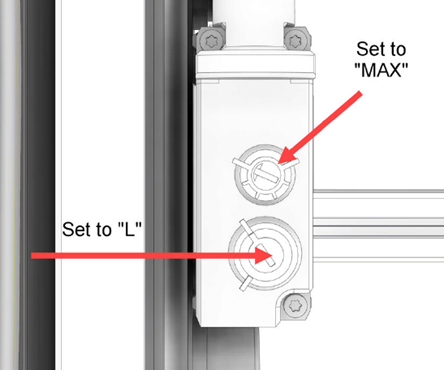
- Set the upper dial to "MAX"
- Set the lower dial to "L“
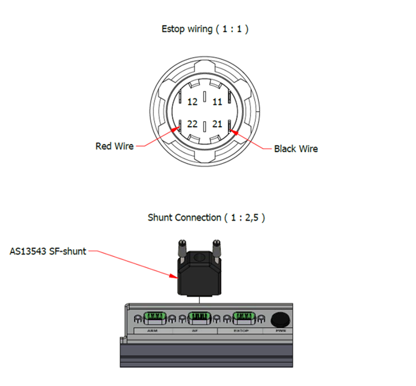
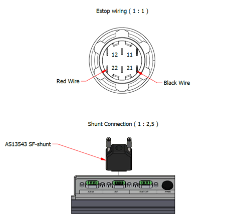
- Ensure E-Stop Connected as required.
- Black Wire Pin 21
- Red wire Pin 22
- Ensure E-stop Operating as expected.
- Continuity test between pins before/after actuation.
- Check e-stop to interface cable.
- Check Motor encoder connections correctly in sockets.
- Make sure there are no bent pins.
- Attach Power cable
Post-Power Checks
- Ensure correct FW on Port controller and Motor Driver Box
- If error 209- Could_not_start_belt_driver go to Motor Driver Box Trouble shooting
- Ensure correct ID ASDriver address and Port IP is correct using Hardware Config.
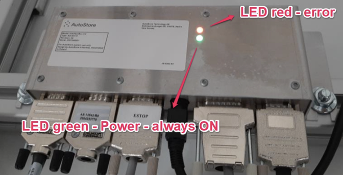
- Is light on Interface box on?
- Connect port to Ethernet and verify connection to system.
- Request information from AS Console.
- Activate Emergency stop and validate that this is communicated to system in “Port” TAB in AS Console
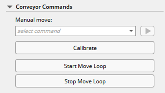
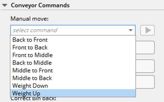
- Manually move Lift table using Conveyor Commands in “Port” TAB in AS Console(Up, Down)
- Manually move Conveyor using Conveyor Commands in “Port” TAB in AS Console (Back, Middle, Front)
- A bin can be placed on the conveyor for this exercise.
- Calibrate conveyor using Conveyor Commands in “Port” TAB in AS Console (Calibrate)
- Use procedure in manuals.
- Use procedure in manuals.
Reset Port Controller
Port Controller factory reset procedure should be used if there are issues with applying FW to port controller or Motor Driver Box:
You can return the Port to its standard settings with the buttons on the Control Panel. To reset the Port to its factory settings:
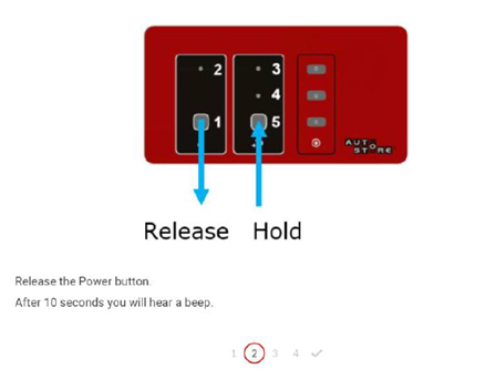
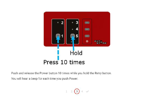
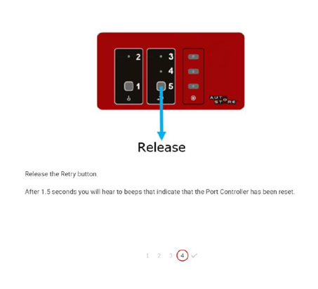
NOTE: If you do not hear two beeps, the Port Controller has not been reset. In this case, repeat the procedure from step one.
Motor Driver Box Troubleshooting
- Check Motor Driver Box Fuse
- Check all parts of Emergency Stop are working and connected.
- Emergency stop on control panel (Wired correctly, Test with Multimeter)
- SF Shunt on interface box (Wired correctly, Test with Multimeter)
- Carry out Reset Port Controller
- Reprogramme Port controller with latest FW
- Ensure correct ID, ASDriver address, IP Port and Port ID is correct.
- Is light on Interface box on?
- Test output from Interface box
- Verify all cables and connections
- Program Motor Driver Box with AVR
- Please observe Fuse settings
- https://crm.autostoresystem.com/service/s/article/Module-Firmware-Fuse-Settings
- Remove Motor driver box from conveyor
- Connect cable AS-13391 to motor driver box and test Pin 6 Of programming connectors.
- Should measure close to +5V in relation to Grnd.
- Ground connection can be referenced from mounting screw for PCB
- Check Fuse
- If +5V, program with AVR
- If below +3.5V, Supply of power not working -> Step 11
- Disconnect AS-13391 and apply power cable from main port power supply.
- Should measure close to +5V in relation to Grnd.
- Ground connection can be referenced from mounting screw for PCB
- Check Fuse
- If +5V, program with AVR
- If below +3.5V, Supply of power not working
- Ensure power Supply working
- Replace Motor Driver Box
- Leave Main port Power connected and attach Data connector from AS-13391
- Check Communication with Motor driver box with HW Config.
- Check Communication with Motor driver box Request Info with AS Console.
- Data should be populated.
- If you get a "Timeout" from the Motor Driver Box after Updating via Hardware Config,
- Remove Motor Driver Box from the Conveyor Port
- Connect to the MDB with the AVR connection cable
- Establish connection to the CPU
- Check the fuse settings and correct them according to the AutoStore recommendations
- Update the FW of the Motor Driver Box (see instructions here under "AVR Programming Tool" https://kardexsolutionsllc.freshdesk.com/en/support/solutions/articles/151000143541-autostore-software-firmware-update-instructions)
Interface Box Troubleshooting
- Is Main Power supply AS16777 connected?
- Is power light on Transformer between plug and connector?
- Is light on Interface box on?
- Green = Power on
- Red = Error
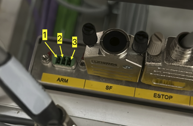
- Test Voltage produced by ARM should be as below
- +24V
- 0V (GND)
- Not to be measured
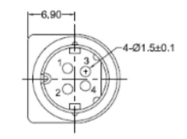
- Check SF (Shunt) on connector AS-13543 Interface Box 2.0, SF-shunt
- Continuity between pin 2->3
- No Connection between pin 1->3
- No Connection between pin 1->2
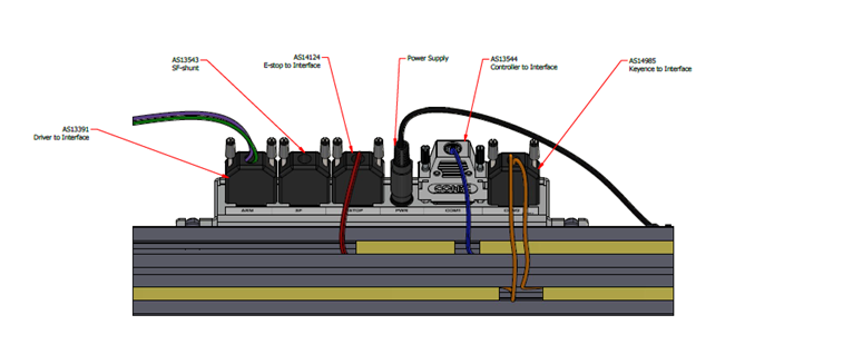

Troubleshooting for Cable from Interface Box to MDB
- Remove the AS-13391 cable only from the MDB side.
- Is AS-13391 correctly connected to the Interface Box ?
- Is the orientation correct? It is possible to "brute force" the connector into the Interface Box incorrectly, which may cause damage.
- Requires a Multimeter with small probe.
- Be aware of short circuits as the pins are small and close to each other.
- On the MDB side, Test Voltage produced by the Power Supply connector should be as below
- Pins 2-1 : +24V
- Pins 4-3 : +24V
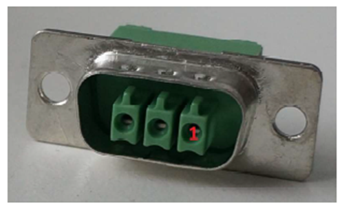
Troubleshooting for Cable from E-stop to Interface Box
- Remove cable at interface box E-stop<=>Interface cable AS-14124
- May require access to back of connector for suitable measuring points
- Estop in Normal state (Not Pressed)
- Continuity between pin 1->2
- No Connection between pin 1->3
- No Connection between pin 2->3
- Estop in Activated state (Pressed)
- No Connection between pin 1->2
- No Connection between pin 1->3
- No Connection between pin 2->3
Was this article helpful?
That’s Great!
Thank you for your feedback
Sorry! We couldn't be helpful
Thank you for your feedback
Feedback sent
We appreciate your effort and will try to fix the article